With the commercial promotion of 5G, the application requirements of eMBB/URLLC such as 4K/8K HD video, cloud game, remote driving and industry control are becoming more urgent. They impose ultra-low latency and ultra-large bandwidth requirements on the network. These performance requirements are closely related to the user plane and require the user plane to provide efficient data processing and forwarding.
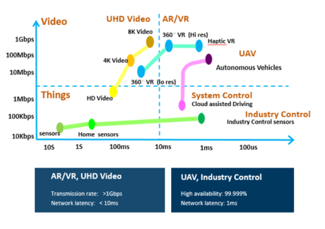
Figure 1 Performance Requirements of Typical 5G Scenarios on Network
However, with the decoupling of software from hardware, the adoption of COTS hardware, and the gradual popularization of network function virtualization in the telecom field, on the one hand, the cost is reduced, improving the resource utilization ratio; on the other hand, the performance of 5G is lower than that of the traditional dedicated hardware and dedicated networks. Therefore, the virtualized pure software user plane cannot meet the requirements of 5G URLLC and some eMBB.
Point and plane are combined to accelerate the 5G user plane
The end-to-end performance improvement of 5G user plane involves many aspects.
First, it is necessary to analyze and optimize the entire network from the perspective of network architecture design and deployment layer to make the user-plane transmission path as short as possible.
Second, it is necessary to optimize the NEs/network functions that forward user-plane data in the network to improve the processing performance of a single node.
This is a process of performance improvement from "plane" and "point."
“Plane”: The CUPS-based user plane is deployed to the edge to shorten the forward path
After a mobile terminal is connected to the core network through a wireless base station, if the core network is not distributed, the service data accessed by the terminal needs to be forwarded through a centralized DC. If the user is in a remote town or village, the latency is doomed to be large.
To improve the forwarding performance of the user plane, the core network must be deployed in distributed mode with respect to the networking architecture. As shown in the following figure, multi-level DCs are deployed on demand in the core network. Compared with central DC, edge DC and access DC are closer to end users, and control-plane signaling messages are still sent to the central DC for processing. User-plane data is directly processed and distributed on the edge or access DC, greatly reducing end-to-end network transmission paths, saving transmission costs and reducing transmission latency.
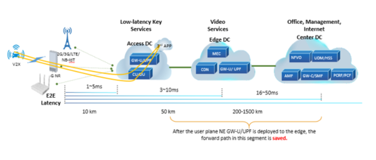
Figure 2 Distributed DC
After core network is deployed in distributed mode, the user plane of core network needs to be separated from the control plane (CUPS) with respect to lightweight edge deployment and management, and only the user plane needs to be moved to the edge on demand.
CUPS has many advantages. On the one hand, the control function is decoupled from the forwarding function, and software management/update is simple and independent. On the other hand, the control plane maximizes the resource utilization in a centralized mode, and the user plane after being decoupled is deployed to the edge to reduce the requirements for edge resources.
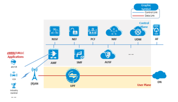
Figure 3 Natural CUPS Architecture of 5G
Therefore, the CUPS-based distributed networking and user plane are deployed to the edge on demand. By reducing the length of the forwarding path, the data forwarding efficiency is improved to some extent. To improve the end-to-end performance of the user plane, the combination of "point" and "plane" is required. Is there room for improving the performance of each forwarding point in the core network? With the trend of virtualization, GW-U/UPF is deployed on the basis of X86 architecture server, so its performance cannot compete with that of dedicated hardware. Telecom operators and vendors urgently need to improve the performance of "point".
“Point”: Software architecture and logic are optimized to improve forwarding performance
For a single user-plane NE vGW-U or UPF, its data processing and forwarding performance factors mainly include service logic complexity (DPI depth, charging and traffic statistics policy), number of packets included in the data flow, packet size, and CPU performance.
Technologies such as DPDK, NUMA binding, OS optimization and huge page are widely used in the industry for vGW-U/UPF performance optimization. In addition, some vendors are also optimizing the software architecture and logic of user-plane NEs. Based on the VPP (Vector Packet Processing) principle, ZTE vGW-U/UPF adopts such technologies as message multi-queue non-lock processing, DPI of the first service packet, and flow table to process and forward hot topic packets in batches, thus effectively reducing the consumption of service logic on CPU. Of course, the performance of unloading user-plane traffic is closely related to the actual service model. The more packets a single flow has, the higher the efficiency of unloading and forwarding is. For example, based on this solution, the video data forwarding efficiency is high.
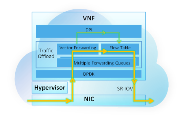
Figure 4 Pure Software Accelerated vGW-U/UPF
Based on the X86 universal server (Its CPU is no less than Intel 6138, and it has dual sockets), ZTE vGW-U/UPF/GW-U with pure software for acceleration can provide a 60Gbps throughput with the latency of less than 100us. It has excellent performance under the same conditions in the industry and can meet the eMBB requirements in both 4G and early 5G.
“Point”: Smart NIC accelerates the virtualized user plane as the weapon of URLLC for success
For ultra-low latency applications such as industry control and self-driving, the pure software user plane based on X86 server is not up to its performance requirements. There are multiple different solutions in the industry. Currently, some GW-U/UPF equipment vendors still advocate the user plane based on dedicated hardware in the 5G solution. With the trend of generalization and virtualization, ZTE promotes the X86-server-based FPGA smart NIC to accelerate the virtualization user plane, providing similar performance to dedicated hardware.
ZTE FPGA smart NIC based vGW-U/UPF learns the first service packet at the software VNF layer, generates a forwarding flow table and sends the flow table to the smart NIC. The subsequent data packets of the same flow will be received, unpacked and forwarded by the smart NIC after being processed, thus reducing the depth of forwarding and processing in the node, greatly reducing the bottlenecks in CPU computing, memory reading and PCIe bus, and improving the performance density of a single server.

Figure 5 FPGA Smart NIC Accelerated Virtualized User Plane
Compared with the vGW-U/UPF accelerated by pure software, the vGW-U/UPF accelerated by the smart NIC has broken through the performance and latency bottleneck of the current virtualized forwarding, thus achieving the ultra-high performance and ultra-low latency of virtualization. The throughput of a single server has been increased to 3 times (180Gbps), its latency has been reduced by 90% (lower than 10us), the power consumption of per Gbit has been reduced by 55%, and its performance is leading in the industry.
The logic of the FPGA smart NIC is strongly related to the logic of vGW-U/UPF. Therefore, the decoupling of the smart NIC from the VNF is the problem that should be faced at present. In the context of virtualization, this is a step that must be taken. Currently, ZTE is actively working with China Mobile to promote the standardization. At the MWC 2019 Shanghai, China Mobile, ZTE and Lenovo jointly carried out the decoupling test of the smart NIC and VNF.
A journey of thousands of miles starts with one step
The user plane is only a part of the communication network, but it carries the traffic of services.
Based on years of technological accumulation, ZTE will work with more partners to explore and promote the maturity of new technologies and new solutions, and push the improvement of 5G and future network capabilities to build a better future.
ZTE supports AI with full-stack IT offering
5GC Green Engine Solution to Enable Green Internet of Everything in the Dual-Carbon Era
5GC Private Network 2.0 Empowerment and Efficiency Improvement Boosts High-Quality Development of the Industry
5G Empowers Intelligent Mining for High-quality Development of Shaanxi Coal Caojiatan Mining
ZTE and China Mobile embrace digitalization for biodiversity conservation in Panda Reserve
Three Aspects Contribute to ZTE’s Remarkable Breakthroughs in Advanced G4X Server
How 5G Private Networks Are Poised to Transform Enterprises Worldwide: All Scenario Private 5G Helps Operators to Realize Private 5G as a Service
ZTE’s commitment to servers generates robust growth of up to 60 times in past 8 years
ZTE eyes top 5 global server market share
Full-Scenario One-Stop 5G Private Network for Vertical Industries