For a closed park or enterprise network, MEC solution distributes the internal network traffic of the park or enterprise to implement local management and operation of the enterprise network, thus to meet the demands of real-time, high-bandwidth, and high-security requirements for mobile office, video monitoring, and on-site data collection inside the enterprise.
How to deploy MEC NEs conveniently and quickly, and realize flexible and efficient distribution without impacting on the existing network is a key issue for carriers to consider.
Solution Description
At present, there are two mainstream 4G distribution technologies: TOF+ and CUPS. There are three mainstream 5G distribution technologies: LADN solution, UL-CL solution and Multi-homing solution.
1. 4G MEC distribution technology
- TOF+ (SGW Offloading +LBO distribution): This solution has the least impact on the existing network. SGW can be deployed with MEC to implement LBO (local break out) function through the SGW enhancement.
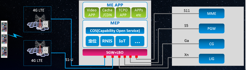
Figure 1 SGW Offloading +LBO Flow Distribution
As shown in the figure, the combination of SGW-U and LBO (enhanced SGW-U function) supports IP address detection of uplink data packets, thus implementing data distribution and local unloading.
SGW-U provides the following functions: Identifying the IP address of the uplink data packet, and transmitting the data packet that complies with local distribution to the LBO. Downlink data from the LBO is integrated with the downlink data from the core PGW-U. Implementing the charging function of local traffic distribution. The lawful interception function for local traffic distribution is also implemented.
LBO functions include: Unloading the data distributed by the SGW-U to the local data network, encapsulating the downlink data flow from the local to the corresponding bearer, and transmitting the data to the SGW-U as GTP-U tunnel packets.
- CUPS distribution: CUPS solution requires deployment of CU separation. GW-C is deployed in the core equipment room, and GW-U is deployed in the edge equipment room. MEC distribution is implemented through the distribution function on GW-U.
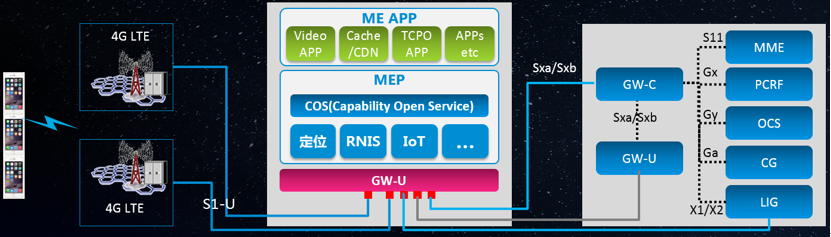
Figure 2 CUPS Distribution
As shown in the figure, in the CUPS distribution, NE functions and external service interfaces of the gateway (GW-C+GW-U) after CU separation are not changed. There is no need to transform adjacent NEs (such as UE and RAN), and they can be interconnected with each NE in the existing network normally. GW-C is connected with adjacent equipment through the unified outgoing signaling interface to simplify network deployment.
- 4G MEC accounting strategy:
It uses SGW (new) to support data distribution, and interconnects with the original MME, PGW, and CG. On the basis of original SGW charging, the requirements for distributed traffic charging are added. For example, for a user, some traffic is distributed to the MEC, and the remaining traffic is sent to the PGW. In this case, the CG must be able to distinguish the distributed traffic.
At present, 3GPP does not define how to charge for MEC distribution in the 4G access scenario, and this needs to be redefined by carriers. Add MEC traffic fields in the existing SGW CDRs by referring to the solution for increasing 5G traffic in the NSA architecture. Before the charging center can identify new MEC traffic fields, CG filters the MEC traffic fields and does not output them. If the CG supports differentiated charging based on the MEC traffic, CG outputs the MEC traffic fields.
2. 5G MEC distribution technology
Based on the C/U separation architecture of the 5G core network, the UPF needs to be deployed at the network edge to reduce the transmission delay and implement local distribution of data traffic. Control-plane functional NEs, such as the SMF, is deployed in the central DC in a centralized manner to control the UPF deployed in the MEC, configure and deliver traffic distribution policies.
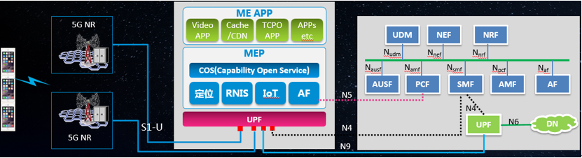
Figure 3 UPF Distribution
5G user plane UPF is deployed to implement local offloading. Local MEC AF informs the PCF of the UPF traffic distribution rule through the N5/N33 interface. PCF configures the traffic distribution policy to the SMF, and SMF performs centralized scheduling of all traffic. It uses such solutions as LADN (Local Area Data Network), UL-CL (Uplink Classifier) or Multi-Homing traffic distribution to implement the traffic distribution of the edge UPF, and unload the local traffic to be distributed through the local edge UPF. Non-local traffic is sent to the central UPF through the local UPF for processing. This avoids alternative traffic to central networks, reduces the pressure of backbone network transmission and network construction costs, improves on-net packet data bearing efficiency and user experience.
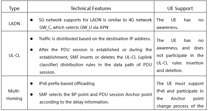
- LADN: LADN is designed associated with regional services or applications. When a user uses the application, the user accesses the application through LADN. When the user location is not in the LADN service area, the user cannot access the LADN, the access DN through the LADN PDU session is only valid in the specific LADN service area. LAND service area is identified by a group of TA. Supporting LADN is a 5G session management mechanism that supports edge computing. When the LADN is used for edge computing traffic distribution, the service areas of the LADN and the single edge computing platform are corresponsible.

Figure 4 LADN Distribution
- UL-CL offloading: When the PDU session type is IPv4, IPv6, IPv4v6 or Ethernet, SMF may decide to insert "UL CL" (Uplink classifier) into the data path of PDU session. UPF supporting UL CL distributes some traffic by matching the flow filters provided by the SMF.
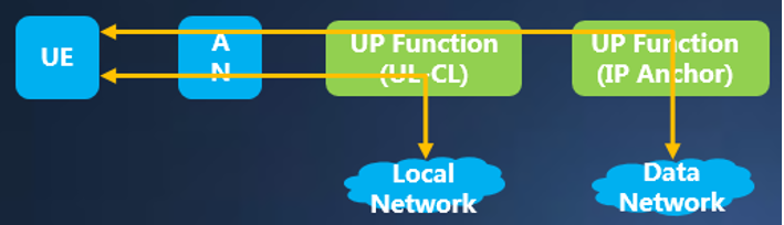
Figure 5 UL-CL Distribution
Multi-Homing distribution: One PDU session may be associated with multiple IPv6 prefixes, which are multi-homing PDU sessions. Multi-homing PDU session, which provides access to the DN through multiple PDU session anchors. Different user plane paths to different PDU session anchors form branches in the "common" UPF. The public UPF is called the UPF that supports "Branching Point" function. Branching Point forwards the uplink traffic to different PDU session anchors and aggregates the downlink traffic sent to the UE. That is, it aggregates the traffic sent from different PDU session anchors to the UE.
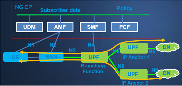
Figure 6 Multi-Homing Distribution
Comparison between Three 5G Distribution Technologies
5G mobile communication technology better supports the MEC in the natural architecture. UPF can be flexibly inserted into each node of the network, making the architecture more flexible and dynamic. MEC+ slicing network coordination enables end-to-end SLA for different service scenarios or industry customers, and realizes enterprise-customized virtualized private network.
Customer Benefits
ZTE's flexible and efficient MEC distribution solution provides virtual private network services with high-performance, high-confidentiality, low-latency, low-cost, construction-free and maintenance-free, meeting the demands of "light assets" in closed parks or enterprise parks. Together with other government and enterprise service products, ZTE provides a full range of services from fixed network to the mobile network, from PC end to mobile end, improving customer satisfaction, network availability, and service usage.
ZTE Common Edge enables 5G network
Intelligent Penetration Test Boosts 5G Security
What Voice Solutions and Applications are Needed in the 5G Era?
ZTE Full-Scene UPF, Simplified and On-Demand
Build new IP interworking gateway offices to promote the deployment of IMS in all networks
5G Standards are Becoming Mature with Smooth Development of R16 and R17
ZTE Promotes the Performance and Efficiency of Servers and Storage to Help Enterprises Dig Deeper into Data Value
5G Operations Get Smarter When AI and Slicing Combine
Virtualized User Plane I/O Performance Acceleration Technology Boosts 5G Network
Whether Deployment is Centralized when VoLTE is Virtualized?