Gateway offices in existing communication networks are set by operators separately, and are responsible for external interworking of their own networks. Although IMS networks are widely deployed by operators, interworking between IMS networks still needs to pass through existing gateway offices. However, existing gateway offices belong to the CS domain, which feature in low transmission and expansion efficiency and poor user experience, so they cannot meet market and user requirements. It is becoming more and more urgent for IMS networks directly interworking through IP.
System Architecture
According to current market requirements, IMS services of operators should be carried and interconnected through the IP data network, and services on existing gateway office should be gradually cut over to IP gateway offices. In addition, the IMS core network and the CS domain must be interconnected.
The interconnection between IMS networks of different operators are shown as below. Operator A adds a pair of IBCF & TrGW (called IP gateway office) to interconnect with the peer office of operator B to implement direct interworking between IMS networks.
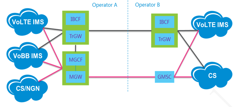
Figure 1 Interworking Between IMS Networks of Different Operators
IP gateway offices provide end-to-end IMS service applications, and support interconnection of high-definition voice and video and other services across different operators’ networks, meeting the latest technical requirements and service requirements.
Networking Planning
The following uses operator A's IP gateway office pilot as an example.
1. Traffic model
The required capacity specifications of interconnected devices are as follows:
- Operator A- Operator B: 114,000 ERL, Operator A- Operator C: 84,000 ERL
- Average call duration ACD = 60s
- Transcoding TC% = 50%;
- Supports media conversion between G.711, AMR and AMR-WB.
- Supports all rate sets of AMR and AMR-WB.
2. IMS interconnection NE
The interconnection NE consists of two modules: IBCF and TrGW.
- IBCF: It implements signaling interworking of voice, video and multimedia services, provides topology hiding and IP security protection, and provides simple number analysis route, normalization transformation and blacklist/whitelist function.
- TrGW: It implements media interworking of voice, video and multimedia services, provides topology hiding and IP security protection, supports voice codec conversion such as AMR/G.711, and transparently transmits various video codecs.
3. Network reliability
To improve the reliability of interconnected networks, the networking of IBCF & TrGW is shown in the following figure.
- Different operators’ IBCF & TrGW interconnect through the private line via the BG.
- To meet network security and remote disaster recovery requirements, BG devices are configured in pairs.
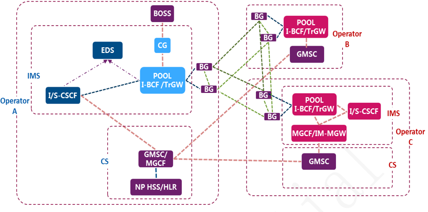
Figure 2 Networking of Different Operators’ IBCF & TrGW
The networking of Operator A’s IBCF Pool is as shown below.
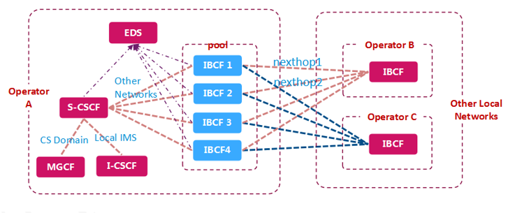
Figure 3 IBCF Pool Networking
- Four sets of IBCF & TrGW are created to compose a pool, which can be selected by the IMS in case of cross-operator.
- Each set of IBCF is configured with route to support interworking of different operators.
- Each set of IBCF&TrGW is configured with one pair of SPE and four pairs of MPE (30,000 users concurrently).
-Each pair of MPE corresponds to 4 ETCB (in 3+1 mode).
4. Charging
The IBCF should support generating CDR to complete the settlement between different operators.
As a new interworking NE, IBCF has been formulated with new charging specifications by operators. In addition to the required fields specified by the IMS network (e.g., ICID, number and media type), the ibcfTrunkGroupID parameter that marks interworking operators is added to the CDR generated by IBCF. To provide charging and settlement function, it is necessary to obtain the location information of the calling party, which is provided by the access Network Information field in the CDR.
Four sets of CGs connected with IBCF are built for the operator network. To improve the network stability, their connection is in active/standby mode, as shown below.

5. Network management
To manage new IBCF & TrGW NEs, operator A upgrades the existing EMS and switches the existing northbound interface specifications to the latest specifications to adapt new NE types. The following figure shows the network connection of the existing EMS.
To support new NE access, operator A has formulated new northbound interface specifications for IBCF & TrGW, and supports NRM (network resource management) and PM (performance management). The NRM can fully detect the configuration information of NEs. The PM provides statistical information about call sessions, interfaces, and system resource usage.
6. Number Portability (NP)
To implement the NP service, operators have defined their own Number Portability Routing Numbers (RN). If the network supports the NP service, ENUM should subscribe the RN prefix for mobile number and provides the home domain name. In an interworking call, the IBCF adds RN to the mobile called number contained in the message as routing information.
Service Test
To ensure the quality of interworking, IBCF & TrGW need to fully undertake functions of the existing gateway office GMSC/MGCF. Domestic operators have tested IBCF & TrGW products and the existing network service cases in detail to ensure that the user experience will not be degraded after cutover.
Network service tests include:
- Exceptional tone playing
- Basic calls: audio, video, V-network user calls, etc.
- Supplementary services: CFU/CFB/CFNRy/CFNRc, multi-party call, call waiting/hold, number display, barring, etc.
- Fax and POS services
- Value-added services: audio CRBT, video CRBT, color printing, etc.
Commercial Cutover
The following figure shows the cutover mode between the IMS network of operator A in different cities and other operators. Before the cutover, the IMS interworks with other operators through the GMSC in the CS domain. After cutover, the IMS directly interworks with the IBCF of other operators through the IBCF (no longer passing through the CS domain).
The I/S-CSCFs in the IMS network group POOLs in different cities. When the IBCF receives a call, it performs number analysis in the way similar to the GMSC, determines the home city of the user through H code, and then selects the POOL of the corresponding I/S-CSCF.
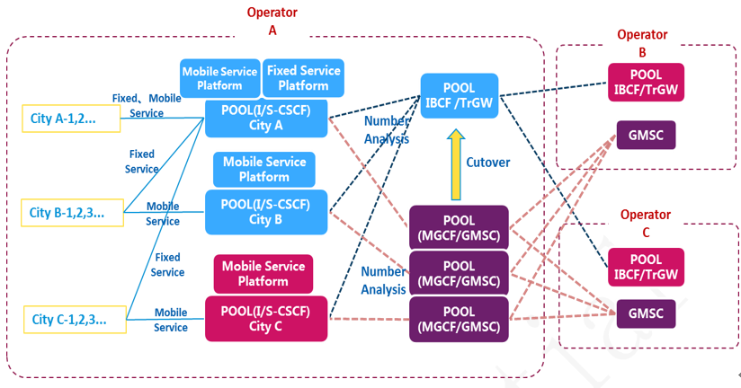
Figure 6 City Traffic Cutover
Conclusion
At present, this IP gateway office pilot is still in progress. According to the schedule, operator A's call dialing tests will be completed soon. After the system is put into trial operation, inter-network call quality will be greatly improved, inter-network services will be more diversified, and user experience will be improved significantly.
ZTE Common Edge enables 5G network
Intelligent Penetration Test Boosts 5G Security
What Voice Solutions and Applications are Needed in the 5G Era?
ZTE Full-Scene UPF, Simplified and On-Demand
5G Standards are Becoming Mature with Smooth Development of R16 and R17
Flexible and Highly-efficient MEC Distribution Solution Enables Industry Customers to Customize a Private Virtualized Mobile Network
ZTE Promotes the Performance and Efficiency of Servers and Storage to Help Enterprises Dig Deeper into Data Value
5G Operations Get Smarter When AI and Slicing Combine
Virtualized User Plane I/O Performance Acceleration Technology Boosts 5G Network
Whether Deployment is Centralized when VoLTE is Virtualized?